


Description
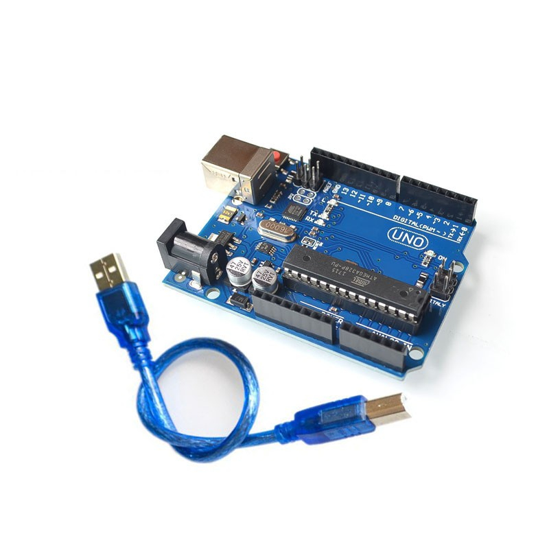
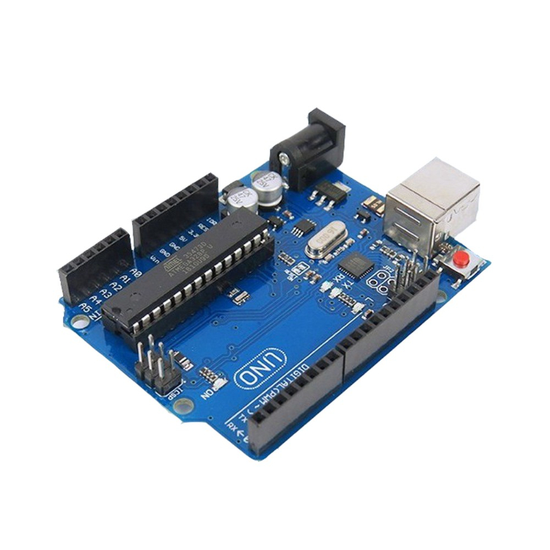
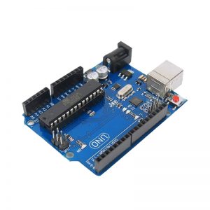
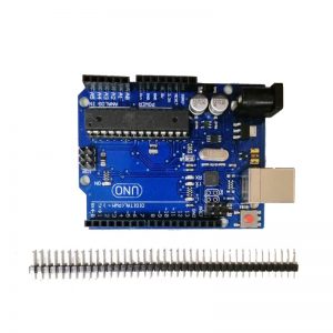
Arduino Uno is a microcontroller board based on the ATmega328P. It has 14 digital input/output pins (of which 6 can be used as PWM outputs), 6 analog inputs, a 16 MHz ceramic resonator (CSTCE16M0V53-R0), a USB connection, a power jack, an ICSP header and a reset button. It contains everything needed to support the microcontroller; simply connect it to a computer with a USB cable or power it with a AC-to-DC adapter or battery to get started.. You can tinker with your Uno without worrying too much about doing something wrong, worst case scenario you can replace the chip for a few dollars and start over again.
“Uno” means one in Italian and was chosen to mark the release of Arduino Software (IDE) 1.0. The Uno board and version 1.0 of Arduino Software (IDE) were the reference versions of Arduino, now evolved to newer releases. The Uno board is the first in a series of USB Arduino boards, and the reference model for the Arduino platform; for an extensive list of current, past or outdated boards see the Arduino index of boards.
- Microcontroller: Microchip ATmega328P[7]
- Operating Voltage: 5 Volts
- Input Voltage: 7 to 20 Volts
- Digital I/O Pins: 14 (of which 6 can provide PWM output)
- PWM Pins: 6 (Pin # 3, 5, 6, 9, 10 and 11)[9]
- UART: 1
- I2C: 1
- SPI: 1
- Analog Input Pins: 6
- DC Current per I/O Pin: 20 mA
- DC Current for 3.3V Pin: 50 mA
- Flash Memory: 32 KB of which 0.5 KB used by bootloader
- SRAM: 2 KB
- EEPROM: 1 KB
- Clock Speed: 16 MHz
- Length: 68.6 mm
- Width: 53.4 mm
- Weight: 25 g
- ICSP Header: Yes
- Power Sources: DC Power Jack & USB Port
General pin functions
- LED: There is a built-in LED driven by digital pin 13. When the pin is high value, the LED is on, when the pin is low, it is off.
- VIN: The input voltage to the Arduino/Genuino board when it is using an external power source (as opposed to 5 volts from the USB connection or other regulated power source). You can supply voltage through this pin, or, if supplying voltage via the power jack, access it through this pin.
- 5V: This pin outputs a regulated 5V from the regulator on the board. The board can be supplied with power either from the DC power jack (7 – 20V), the USB connector (5V), or the VIN pin of the board (7-20V). Supplying voltage via the 5V or 3.3V pins bypasses the regulator, and can damage the board.
- 3V3: A 3.3 volt supply generated by the on-board regulator. Maximum current draw is 50 mA.
- GND: Ground pins.
- IOREF: This pin on the Arduino/Genuino board provides the voltage reference with which the microcontroller operates. A properly configured shield can read the IOREF pin voltage and select the appropriate power source, or enable voltage translators on the outputs to work with the 5V or 3.3V.
- Reset: Typically used to add a reset button to shields that block the one on the board.
Special pin functions
Each of the 14 digital pins and 6 analog pins on the Uno can be used as an input or output, under software control (using pinMode(), digitalWrite(), and digitalRead() functions). They operate at 5 volts. Each pin can provide or receive 20 mA as the recommended operating condition and has an internal pull-up resistor (disconnected by default) of 20-50K ohm. A maximum of 40mA must not be exceeded on any I/O pin to avoid permanent damage to the microcontroller. The Uno has 6 analog inputs, labeled A0 through A5; each provides 10 bits of resolution (i.e. 1024 different values). By default, they measure from ground to 5 volts, though it is possible to change the upper end of the range using the AREF pin and the analogReference() function.[7]
In addition, some pins have specialized functions:
- Serial / UART: pins 0 (RX) and 1 (TX). Used to receive (RX) and transmit (TX) TTL serial data. These pins are connected to the corresponding pins of the ATmega8U2 USB-to-TTL serial chip.
- External interrupts: pins 2 and 3. These pins can be configured to trigger an interrupt on a low value, a rising or falling edge, or a change in value.
- PWM (pulse-width modulation): pins 3, 5, 6, 9, 10, and 11. Can provide 8-bit PWM output with the analogWrite() function.
- SPI (Serial Peripheral Interface): pins 10 (SS), 11 (MOSI), 12 (MISO), and 13 (SCK). These pins support SPI communication using the SPI library.
- TWI (two-wire interface) / I²C: pin SDA (A4) and pin SCL (A5). Support TWI communication using the Wire library.
- AREF (analog reference): Reference voltage for the analog inputs.[7]
Reviews
There are no reviews yet.